Scout Case Mods for High-Lift Cams & Lifters
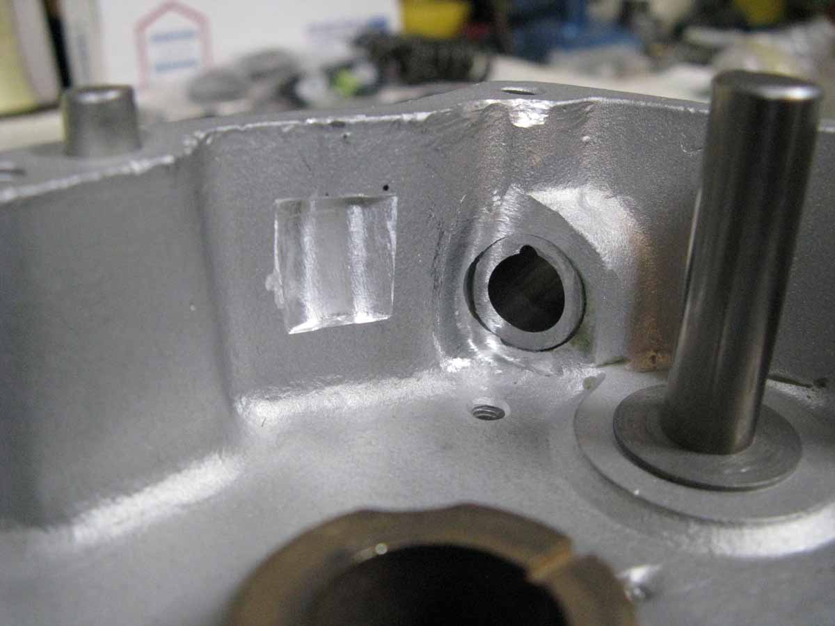
Here you can see (3) seperate mods. The first is the 1/8" hole drilled through the inner case wall at a point where the lifter arched pad meets the bottom of the push rod. You need (4) holes, one each per push rod. Do a small bevel with a 1/4" drill bit at both ends. This is a good mod for lubing the push rods, and lifter. The factory did this on 1952-1953 Chiefs.
The second mod is a grind job at the bottom of the rear cylinder's Exhaust push-rod guide. It needs to be ground in an arched shape like the Exhaust lifter's arched pad. You will need to grind some here, then some in the roller trench (the 3rd case mod). Go back and forth until you get at least .030" of lifter free play from the cam lobe at it's top-of-lift.Take your time, and get the .030" slop at the push-rod guide, and the case wall for the roller at the same time. You need some clearance from the lifter, if you start to get some valve float! More detailed description below.
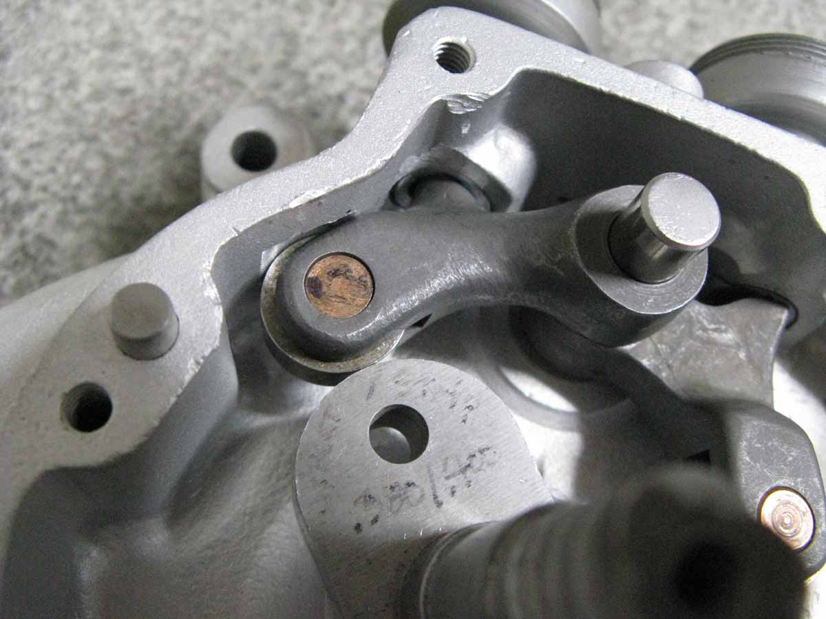
Here you can see the case with the lifters installed. You can't see the .030" clearance, but it is there behind the cam lobe. Look closely at the push-rod guide. Plus, I made the roller trench slightly larger than needed for clearity in the picture. Read more below.
In order to use my High-Lift cams & racing lifters, there is the need for some clearancing inside the cam chest. The factory left very little room inside the cam chest for the lifters to be able to support any kind of extra valve lift. Flat-Heads really like high-lift! I feel the reason that the Bonneville Scouts had very little lift is because they didn't want to have to modify the cam chest? The problem is primarily with the rear cylinder exhaust lifter. Since the front cam is lower, and in contact with the pinion gear, there is plenty of lifter room. But, since the rear cam is raised away from the pinion gear, the rear exhaust lifter comes into contact with the push-rod guide bottom, and the rear case wall at max-lift with my performance cams. To fix this, you need to get a Dremel Tool with a cylindrical grinding bit (around 3/8" OD). You need to grind a radius at the bottom of the guide for clearance from the "Arched Pad" on the lifter. It needs to be ground in a radius that closely follows the shape of the arched pad, while leaving at least .030" clearance from the guide at the cam's max lift. Part of the arched pad can disappear into the hole of the guide. That's OK! You may have to grind some off the bottom of the rear intake push-rod guide, so take a close look at it also.
Then, my new batch of lifters have improved larger OD rollers, and you will need to cut a small trench for the lifter roller to partially disappear into. Again, you must leave at least .030" of free clearance at the cam's max-lift. Use the Dremel Tool with a Carbide cutting barrel (the trench should be about 5/16" wide giving some side clearance from the roller). Do your best surgical job here. Install both the rear cylinder lifters to get the lifter placement correct! Take a look closely at the lifter body for any contact against the cam chest rear wall. You also need the same .030" clearance at max-lift. I like to take my new cam lobe, and partially press it on a used cam shaft, so you can drop it in, and watch the clearances better without the cam/gear in the way. Yes, this is a hassle to do, but it's a small price to pay to Double your power! Look closely at my pictures. Set the roller at the top of the cam lobe, and you should be able to slop the lifter around with it's .030" of clearance.
Another good case mod is drilling (4) 1/8" holes in the cam chest inner wall right at the contact point, where the push-rod contacts the lifter's arched pads (with cam lobe in place). This is good for push-rod, and lifter lubrication. Put a slight bevel at both ends of the drilled holes. Plus, check the cam lobe for clearance from your pinion race "boss".
A very good mod is converting the original "Sump" system over to the 1947 Chief "Scraper". I feel this is an essential mod. It requires only some grinding of the hole, where the scraper goes in. Be very careful to NOT take too much metal away. There is very little gasket surface to work with. I do the right side case first, and do any trimming on the scraper to fit the inside of the case. The scraper will extend left of the case joint, so you will need to grind a little where the scraper crosses over to the left side. The oil scavenging is so much better! Take a look at my "Breather" section in my "Tech-Talk" section to see how I made a re-circulating breather system for my Twin-Scout. This bike doesn't ever lose a drop of oil! It really works well.
I like to replace the cylinder studs with new longer studs. The originals didn't go all the way down the hole, and needs to catch more threads. I use a bottoming tap to clean out the hole, and to get a little more thread. I trim the length to get the stud "bottomed" in the hole. Then I leave some extra threads above the deck, so I can use a thin jam-nut on top of the original base nuts. I use non-lock 3/8" stainless "AN" washers under the base nuts. At very high-RPM, the studs and nuts can come loose!
I am a firm believer in using a timing light for correct ignition timing. The 741 cases (and Chiefs) have a 12 O'Clock position timing inspection hole, but only the latest Scouts have them. When I see an older Scout case, I drill a hole and tap it for (5/8" fine), and I use a Harley-Davidson aftermarket plug. They have some nice plugs, and I use the chromed plug with a hex head. Use some Teflon tape on the threads. Find my page in my CV carb section that describes how to stamp your flywheels as a degree wheel. It makes timing so simple. I leave clear timing plugs (safety wired in) on my Twin-Scout, and I can check the timing in seconds!
CONTACT INFORMATION:
James R. Mosher
(505) 466-7870